The operation and output of the 555 Monostable is exactly the same as that for the transistorised one we look at previously in the Monostable Multivibrators tutorial. The difference this time is that the two transistors have been replaced by the 555 timer device. Consider the 555 Monostable circuit below.
Wednesday, October 12, 2011

Friday, July 29, 2011
LM3915/LM3916 VU Meter

Features
Description
The LM3916 is a monolithic integrated circuit that senses analog voltage levels and drives ten LEDs, LCDs or vacuum fluorescent displays, providing an electronic version of the popular VU meter. One pin changes the display from a bar graph to a moving dot display. LED current drive is regulated and programmable, eliminating the need for current limiting resistors. The whole display system can operate from a single supply as low as 3V or as high as 25V.
The IC contains an adjustable voltage reference and an accurate ten-step voltage divider. The high-impedance input buffer accepts signals down to ground and up to within 1.5V of the positive supply. Further, it needs no protection against inputs of ±35V. The input buffer drives 10 individual comparators referenced to the precision divider. Accuracy is typically better than 0.2 dB.
Audio applications include average or peak level indicators, and power meters. Replacing conventional meters with an LED bar graph results in a faster responding, more rugged display with high visibility that retains the ease of interpretation of an analog display.
The LM3916 is extremely easy to apply. A 1.2V full-scale meter requires only one resistor in addition to the ten LEDs. One more resistor programs the full-scale anywhere from 1.2V to 12V independent of supply voltage. LED brightness is easily controlled with a single pot.
Monday, April 4, 2011
Stereo FM/AM Receiver CXA1538

Description Of Stereo FM/AM Receiver CXA1538
The CXA1538M/N/S is high performance one-chip bipolar ICs designed for FM stereo/AM radios. These include an FM/AM front end, FM/AM IF amplifier, FM/AM detection output and FM stereo demodulator output. Pin 4 is the stereo indicator and VCO check pin. Therefore, in stereo mode (when stereo indicator drive Tr Q2 is switched on), pin 4 voltage lowers down, Q1 is cut off and VCO oscillation waveform can not be seen. In AM mode as well, the oscillation waveform can not be seen as VCO turns off.Adjust the free run frequency at 76 kHz ±50 Hz. This IC has a built-in auto blend circuit and a MONO switch is not required as a rule. This circuit controls the separation in proportion to the signal level and reduces noise automatically for stereo reception below the mid electric field when the electric field strength reaches lower than about 40 dBμ. When the electric field strength turns below 10 to 15 dBμ, MONO operation is automatically activated. To switch MONO mode on externally, ground pin 3 with 33 Kohm. This IC has a built-in soft muting circuit. As shown in the following I/O characteristics diagram, 23 dB (Typ.) muting is applied and noise level reduced during weak electric field and out of tune instances.
Features Of Stereo FM/AM Receiver CXA1538
- Low current consumption (In FM mode ID=11.0 mA, in AM mode 8.5 mA, VCC=6.0 V)
- Built-in LED drive circuit for tuning
- Built-in LED drive circuit for stereo indicator
- Built-in muting circuit for the FM band
- Few external parts
AUDIO POWER METER circuit WITH LM3915

This VU (volume-unit) meter is capable of monitoring and displaying
power levels present at the speaker terminals of a stereo audio
power amplifier.
The levels are displayed in ten discrete steps. This meter is not
designed to give an accurate display of the power levels.It is
designed to give an approximate visual indication of the audio
power output of each channel. For many situations - disco, parties this
is all which is required: the flashing LED's add atmosphere to the
situation.
LM3915. This is a monolithic Dot/Bar Display Driver IC made by
National Semiconductor. It takes an analog voltage input on pin 5
then drives 10 LED's providing a logarithmic 3dB/step analog display.
When measuring power, a 3dB increase means that the power input
has doubled. As the power doubles, an additional LED will be lit until
the maximum is reached. The display can be bar or moving dot
depending on the connection of pin 9 to the positive supply. The LED
drive current is regulated which eliminates the need for current
limiting resistors.
The supply voltage can be between 3V to 25V.
Mini Audio Spectrum Analyzer LM3915

The circuit has been designed to create a spectrum analyzer that will provide an analysis of
a sound to determine at various frequencies, the volume of sounds that make up the overall
sound spectrum.
Wednesday, March 30, 2011
Controlling LED brightness using PWM

Pulse Width Modulation or PWM is a term you hear a lot if you are interested in controlling power output using a microcontroller. It has many applications, although one of the most popular amongst hobbyists is controlling the brightness of LEDs. In this tutorial we will cover the basic principles behind PWM and how it can be used for LED brightness control including fading out LEDs rather than just turning them on and off.
This article will focus on some of the more specific details of the PIC18F range of microcontrollers; however the techniques and principles are the same for all other microcontroller products. Some microcontrollers include PWM modules which perform all of the hard work for you; however this article focuses on the more universal (and scalable) technique of using interrupts.
Thursday, March 10, 2011
InfraRed Proximity Detector

This proximity detector using an infrared detector (Fig. 1) can be used in various equipment like automatic door openers and burglar alarms. The circuit primarily consists of an infrared transmitter and an infrared receiver. The transmitter section consists of a 555 timer IC functioning in astable mode. It is wired as shown in the figure. The output from astable is fed to an infrared LED via resistor R4, which limits its operating current. This circuit provides a frequency output of 38 kHz at 50 per cent duty cycle, which is required for the infrared detector/receiver module. Siemens SFH5110-38 is a much better choice than SFH506-38. Siemens SFH5110-38 is turned on by a continuous frequency of 38 kHz with 50 per cent duty cycle, whereas SFH506 requires a burst frequency of 38k to sense. Hence, SFH5110-38 is used.

The receiver section comprises an infrared receiver module, a 555 monostable multi vibrator, and an LED indicator. Upon reception of infrared signals, 555 timer (mono) turns on and remains on as long as infrared signals are received. When the signals are interrupted, the mono goes off after a few seconds (period=1.1 R7xC6) depending upon the value of R7-C6 combination. Thus if R7=470 kilo-ohms and C6=4.7μF, the mono period will be around 2.5 seconds.
Both the transmitter and the receiver parts can be mounted on a single breadboard or PCB. The infrared receiver must be placed behind the infrared LED to avoid false indication due to infrared leakage. An object moving nearby actually reflects the infrared rays emitted by the infrared LED. The infrared receiver has sensitivity angle (lobe) of 0-60 degrees, hence when the reflected IR ray is sensed, the mono in the receiver part is triggered. The output from the mono may be used in any desired fashion. For example, it can be used to turn on a light when a person comes nearby by energizing a relay. The light would automatically turn off after some time as the person moves away and the mono pulse period is over.
The sensitivity of the detector depends on current-limiting resistor R4 in series with the infrared LED. Range is approximately 40 cm. For 20-ohm value of R4 the object at 25 cm can be sensed, while for 30-ohm value of R4 the sensing range reduces by 22.5 cm.
Tuesday, March 8, 2011
RESISTOR COLOR CODE
A resistor is a two-terminal electrical component used in electronic circuits to oppose the flow of an electric current. If an object inserted in a circuit displays a current flow which is proportional to the voltage across it, the ratio of voltage V divided by current I will be constant. This constant ratio is called resistance R=V/I. It can be measured by a device called ohmmeter. In an ideal resistor R does not depend on the current. The Ohm's law states that I=V/R.
Sunday, March 6, 2011
Parrot Sounding AC door Bell

Friday, March 4, 2011
STK4050V 200 watt amp

This 200 watt amp schematic circuit is based on STK4050V high power audio amplifier IC and is designed do deliver up to 200 watts audio power on a single channel .
STK4050V 200 watt amp audio amplifier IC is pin compatibility with other STK amplifiers series .
Because of current mirror circuit application the distortions are reduced to 0.08 % .
STK4050V supports addition of electronic circuits for thermal shutdown and load-short protection circuit as well as pop noise muting which occurs when the power supply switch is turned on and off.
The maximum output power of STK4050V audio amplifier is around 200 watts on 8 ohms load impedance with a 66 volts split power supply .
If you want to make this power amplifier you need to make a separate thermal protection and load short protection circuit because the IC don’t offer these kind of protection and you can destroy the chip and the speaker box .
Thursday, March 3, 2011
Musical light chaser circuit

Description
Here is a simple state of the art musical chaser circuit that can be used in discotheques or even at home if you are a little music crazy .The working of the circuit is straight forward ,the condenser mic pickup the sound and Q1amplifies it.This signal is fed to clock input of IC1 ,CD 4016.The IC is wired in divide by ten mode.The out put of IC1 is given to clock input of IC2, CD4016.The out puts of IC 2 shown in the right side of IC2 in circuit diagram will run run according to the frequency of the input.Result ,we get 10 lights dancing in the according frequency of the sound available.If no sound is there the first light will glow steady.For saving space only arrangement for connecting only one lamp is shown in the diagram.Make 9 lamp arrangements like the one shown in figure and connect each if them to the each outputs of IC2 with the other ends connected to the circuit as that of one shown in circuit.
The power supply for the circuit is directly derived from the mains itself using D2 , R9,C4,C3 and D3, which adds an extra bonus of avoiding the bulky transformer to make the circuit compact.
- If the output doesn't respond to the music and only the first light remains glowing, adjust the level of input signal to IC1 by adjusting R1 since the cause of problem is the low voltage level of input to IC1.Problem is solved.
- Some parts of the circuit are live with potential shock hazard.So be careful.
Sound Level Meter

Description
This is a one chip sound level meter that can be use for displaying sound level of an amplifier or simply the sound level from a microphone.The heart of the circuit is IC LM 3915 Audio level IC.Even though it is a stand alone IC , a peak detector based on Transistor BC 558 and diode 1N4001 is also included for better performance.
Tips
Supply voltage can be from 3V to 20V.The input is set for audio line voltage (1V peak to peak) and has a max input voltage of 1.3V. To make the circuit use a moving dot display instead of bar graph display,Pin 9 can be should be disconnected from +V.
Parts List.C1 2.2uF 25V Electrolytic Capacitor
C2, C3 0.1uF Ceramic Disc Capacitor
R1, R3 1K 1/4W Resistor
R2 10K 1/4W Resistor
R4 100K 1/4W Resistor
R5 1M 1/4W Resistor
D1 1N4001 Silicon Diode
Q1 BC 558 PNP Transistor
LED1-LED10 Standard LED or LED Array
U1 LM3915 Audio Level IC
MISC Board, Wire, Socket For U1
Wednesday, March 2, 2011
Ultra Bright LED Lamp
This ultra-bright white LED lamp works on 230V AC with minimal power consumption. It can be used to illuminate VU meters, SWR meters, etc. Ultra-bright LEDs available in the market cost Rs 8 to 15. These LEDs emit a 1000-6000mCd bright white light like welding arc and work on 3 volts, 10 mA. Their maximum voltage is 3.6 volts and the current is 25 mA. Anti-static precautions should be taken when handling the LEDs.
Monday, February 28, 2011
Fading LED by LM358

This circuit uses op-amps to obtain a triangle wave. The triangle wave causes the Led to slowly get brighter and then slowly get dimmer until it isn’t producing any light. It then gets slowly brighter again. With the components shown each cycle takes about 4 seconds. The capacitor and the 4.7M resistor are the timing components. The circuit works best when a high brightness Led is used.
Friday, February 25, 2011
Classic LED Flasher Circuit

This LED flasher circuit is a classic two transistor flip flop. This flasher circuit is very popular and it’s usually the first circuit to build when starting electronic circuit building hobby. Here is the schematic diagram of the famous LED flasher circuit:
Tuesday, December 14, 2010
Emergency Light & Alarm
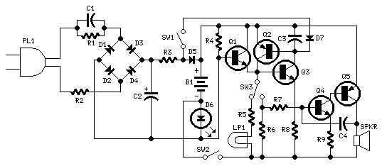
Device purpose:
This circuit is permanently plugged into a mains socket and NI-CD batteries are trickle-charged. When a power outage occurs, the lamp automatically illuminates. Instead of illuminating a lamp, an alarm sounder can be chosen.
When power supply is restored, the lamp or the alarm is switched-off. A switch provides a "latch-up" function, in order to extend lamp or alarm operation even when power is restored.
When power supply is restored, the lamp or the alarm is switched-off. A switch provides a "latch-up" function, in order to extend lamp or alarm operation even when power is restored.
Circuit operation:
Mains voltage is reduced to about 12V DC at C2's terminals, by means of the reactance of C1 and the diode bridge (D1-D4). Thus avoids the use of a mains transformer.
Trickle-charging current for the battery B1 is provided by the series resistor R3, D5 and the green LED D6 that also monitors the presence of mains supply and correct battery charging.
Q2 & Q3 form a self-latching pair that start operating when a power outage occurs. In this case, Q1 biasing becomes positive, so this transistor turns on the self latching pair.
If SW3 is set as shown in the circuit diagram, the lamp illuminates via SW2, which is normally closed; if set the other way, a square wave audio frequency generator formed by Q4, Q5 and related components is activated, driving the loudspeaker.
If SW1 is left open, when mains supply is restored the lamp or the alarm continue to operate. They can be disabled by opening the main on-off switch SW2.
If SW1 is closed, restoration of the mains supply terminates lamp or alarm operation, by applying a positive bias to the Base of Q2.
Trickle-charging current for the battery B1 is provided by the series resistor R3, D5 and the green LED D6 that also monitors the presence of mains supply and correct battery charging.
Q2 & Q3 form a self-latching pair that start operating when a power outage occurs. In this case, Q1 biasing becomes positive, so this transistor turns on the self latching pair.
If SW3 is set as shown in the circuit diagram, the lamp illuminates via SW2, which is normally closed; if set the other way, a square wave audio frequency generator formed by Q4, Q5 and related components is activated, driving the loudspeaker.
If SW1 is left open, when mains supply is restored the lamp or the alarm continue to operate. They can be disabled by opening the main on-off switch SW2.
If SW1 is closed, restoration of the mains supply terminates lamp or alarm operation, by applying a positive bias to the Base of Q2.
Notes:
- Close SW2 after the circuit is plugged.
- Warning! The circuit is connected to 220Vac mains, then some parts in the circuit board are subjected to lethal potential!. Avoid touching the circuit when plugged and enclose it in a plastic box.
Parts:
R1____________220K   1/4W Resistor
R2____________470R   1/2W Resistor
R3____________390R   1/4W Resistor
R4______________1K5  1/4W Resistor
R5______________1R   1/4W Resistor
R6_____________10K   1/4W Resistor
R7____________330K   1/4W Resistor
R8____________470R   1/4W Resistor
R9____________100R   1/4W Resistor

C1____________330nF  400V Polyester Capacitor
C2_____________10µF   63V Electrolytic Capacitor
C3____________100nF   63V Polyester Capacitor
C4_____________10nF   63V Polyester Capacitor

D1-D5________1N4007 1000V 1A Diodes
D6______________LED  Green (any shape)
D7___________1N4148   75V 150mA Diode

Q1,Q3,Q4______BC547   45V 100mA NPN Transistors
Q2,Q5_________BC327   45V 800mA PNP Transistors

SW1,SW2________SPST Switches
SW3____________SPDT Switch

LP1____________2.2V or 2.5V 250-300mA Torch Lamp

SPKR___________8 Ohm Loudspeaker

B1_____________2.5V Battery (two AA NI-CD rechargeable cells wired in series)

PL1____________Male Mains plug
Enjoy.......
Monday, December 13, 2010
LED STEREO SOUND LEVEL INDICATOR
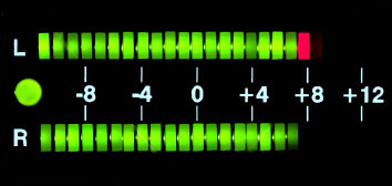
Many circuits can be designed as level indicators by using a comparator IC or transistors but these are costly and complex and also time consuming. This circuit removes all the complexity by using a single TA7666p IC. LEDs are used as a power indicator. Different colour LEDs can be used for both the channels. One can also use an LED bargraph display. INPUT signals should be given from preamplifiers. Otherwise, LEDs will not glow at low volumes.
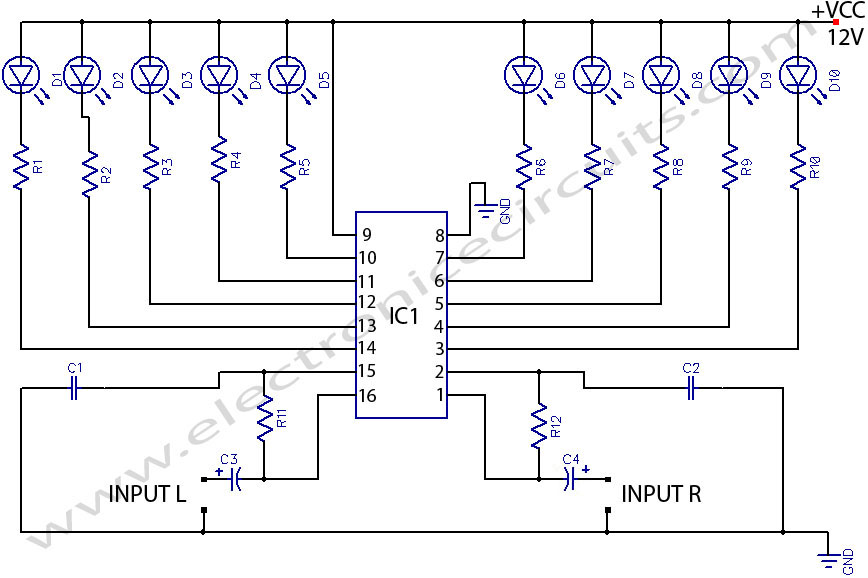
| PARTS LIST | |
| R1-R10 | 1kΩ |
| R11 | 15kΩ |
| R12 | 15kΩ |
| C1 | 0.1µF |
| C2 | 0.1µF |
| C3 | 1µF 16V |
| C4 | 1µF 16V |
| D1-D10 | 10 LEDs |
| IC1 | TA7666P |
If you have mono systems, signals should be given into both the channels. The input is given through two 4.7 µF capacitors and two 18k resistors to pins 1 and 16 respectively.
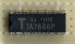
- Suitable for stereo LED driver
- Wide Supply Voltage Range : VCC = 6V to 12V
- Low Quiscent Current : ICCQ = 4ma (typ.) at Vcc = 9V
- Variable Voltage Gain Because of Inverting Amplifier
- Easy Arrangement for Dual 10 LED’s Driver by Series Connection of TA77666P and TA7667P
Audio VU Meter
This circuit uses two quad op-amps to form an eight LED audio level meter. The op-amp used in this particular circuit is the LM324.

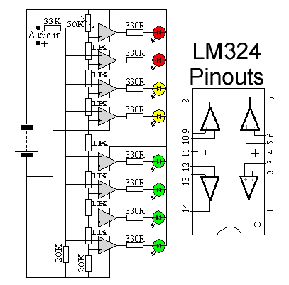
The 1K resistors in the circuit are essential so that the LED's turn on at different audio levels. There is no reason why you can't change these resistors, although anything above 5K may cause some of the LED's to never switch on. This circuit is easily expandable with more op-amps, and is not limited to use with the LM324. Pretty much any op-amp will work as long as you look up the pinouts and make sure everything is properly connected.
The 33K resistor on the schematic is to keep the signal input to the circuit at a low level. It is unlikely you will find a 33K resistor, so the closest you can get should do. The value of this resistor may need to be changed, so it is best you breadboard this circuit before actually constructing it on PCB. The circuit in it's current form will accept line level inputs from sources such as the aux out on a Hi-Fi, all though could be easily modified to accept speaker inputs.
The audio + is connected to the main positive rail, while the audio - is used for signal input. The 50k pot can be used to vary the sensitivity of the circuit.
Thursday, December 9, 2010

Monday, November 29, 2010
Knight Rider Lights Project
This is a simple knight Rider light system that can be built using well known popular integrated circuits.
Circuit diagram for standard LED output.


This set up is ideal for running off a car battery.
You can use 12V bulbs for the output, simply substitute the IC for the LEDs, the bulbs are then connected to the IC's outputs.
Components List
Circuit diagram for standard LED output.


This set up is ideal for running off a car battery.
You can use 12V bulbs for the output, simply substitute the IC for the LEDs, the bulbs are then connected to the IC's outputs.
Components List
PARTS LIST | ||||
| ICs | DIODES | BULBS | RESISTORS | CAPACITORS |
| 1*NE555 | 8* 1N4148 | 6* 1K | 1* 10uF | |
| 1* 4017B | 1* 3.3K | 1* 0.01uF | ||
| 1* 8.2K | 1* 6.8nF | |||
| 6* LED | 1* 10K | |||
| Bulb Version | 1* 100K | |||
| 1* ULN2001N | 6* 12V/2.2W | |||
| Plus 6* suitable Bulb Holders. | ||||
Subscribe to:
Posts (Atom)